Seawater Desalination Plant Lompoul / Senegal
As a result of the decisions taken by board of directors, our company has begun vital humanitarian project that is value of 850.000.000 € regarding with obtaining fresh water by purifying the sea water in the coast of Atlantic Ocean in Senegal - Dakar -Lompoul in Africa.
In this framework, our company has worked on preliminary feasibility processes for two years and commenced the construction for seawater desalination project in Lompoul in order to firstly supply need of fresh water to the city of Dakar and Lompoul.
1. Basic considerations as far as the selection of the procedure is concerned
When selecting the procedure of the seawater desalination the specific energy costs per each ma drinking water and the electrical energy installation cost are the main cost and playing during the selection of the technical procedure a particularly large role. The main part of the total investment is for the seawater desalination plant.Desalination plants of the desired size can be operated thermally (MED, MSF, MVR) or by means of a membrane process (reverse osmosis). The investment costs of a thermal desalination plant is on average about 50% higher than the investment costs of a reverse osmosis system with comparable performance.
In the case of thermal installations, it is necessary to distinguished between MED (multi effect distillation) and MSF (multistage flash) on the one hand, and MVR (Mechanical Vapor Recompression) on the other hand. The first both plant types needed in addition to electrical energy (MED approx. 1.5 - 2.5 kWh / ms, MSF 3 - 5 kWh / ma) also thermal energy in the form of steam (233 - 258 MJ / ma). Technical procedures with mechanical vapor compression are achieved without thermal energy, instead they need: But appr. 10 kWh / m³ of electrical energy.
In comparison to this, a reverse osmosis requires exclusively electrical energy (approx. 2.5 - 3.5 KWh / m) In a direct comparison of the purely electrically operated desalination plants, the energy generation for thermal desalination plants must be built about 3x larger than for reverse osmosis systems be built.
For MED / MSF plants, a two-track power generation must be established. On the one hand the electricity power must be used in the same scale of magnitude as for the reverse osmosis processes, on the other hand, must be installed a solar thermal power plant for steam production. Thus, the cost are minimized of seawater desalination and energy generation in the case of use of reverse osmosis procedure.
2. Process setup
The complete seawater desalination plant is modularly divided into several small units. This offer has the great advantage that maintenance has no influence on drinking water production.The seawater is taken directly from the sea. For this purpose, a removal structure with corresponding coarse filtering sunk directly in the sea, so a removal in about 25 m depth. This has the advantage that the water quality through shipping, tides and storms on the collection site is not affected. Furthermore, no impairment is caused by this depth algae can be expected.
The sea water is extracted from the extraction plant via a PE pipeline to the extraction pumps at the coast. From the frequency-controlled extraction pumps, the water should be pumped over two step multilayer filter. In the multilayer filters, the water is separated from the finest suspended matter and is free from impurities.
The pre-filtered water is metered Sulfuric acid and anti scalant to prevent efflorescence on the membrane. After that it take place a final safety filtration via candle filters before the sea water in the reverse osmosis system to split into a low salt permeate and a salt rich concentrate.
The saline-rich concentrate is further processed in saline to salt. The non-usable concentrate is sent to the sea in an environmentally friendly manner back.
The low-salt permeate must be cured before use as drinking water. To this end, lime milk and chlorine are added to the permeate. This means that the water meets the requirements of WHO for drinking water and is protected against re-germination during transportation on the approximately 100 km pipeline.
3. Technical description of the whole concept
Together with the representatives of the municipality of Lompoul, the location for the new plant was determined. 160,000 m3 of drinking water per day will be produced at this site.The drinking water is directed to Dakar by a new pipeline consisting of 2 parallel pipes DN 1,200, close to the coast. This increases the security of supply and facilitates the rehabilitation of the existing old pipeline at a later date. The total length of the pipeline including the connections to the stock is about 100 km. Due to the generous dimensioning of the pipeline, intermediate pumping stations are not required.
As already described, the sewage is discharged at a depth of approx. 25 m and due to the geographic situation in about 8-10 km from the coast. The extraction pipes and the return pipes as well as the track system to the quay are guided so through the protected forest strip near the coast, that the vegetation practically does not get affected and the pipes end in this area of the site in which the entire technology is in housed. The site was set up in 2012 together with the municipal council of Lompoul (side map).
Parallel to this, a new harbor quay is being installed, which is also planned for the management of the pipeline. The return way of the concentrate at a different point, which is still to be adjusted. About this 8-10 m wide harbor quay with two-sided sheet piling, 2 tracks (outward and return) lead to the saline or to the power stations.
The port facility is designed for mass bulk carriers or bulk carriers until to the Panamax class. This means approximately one coal ship per month and one salt ship per week. This concept ensures that the transport will not be bogged down by the existing infrastructure (roads, local city by pass roads) and will be realized over the open sea.
Ships of the Panamax class have a depth of the ships of 12.50 m. We expect a 5 km-long harbor quay to ensure a natural basin depth of 15-17 m. The port facility can also be used later for the fishermen of Lompoul.
In the central area of technology, the filling plant / beverage factory is also designed for approx. 90,000,000 containers per year (15,000 containers per hour).
Three thermal power blocks of 15 MW are provided for electrical power supply. 2 blocks are in operation and the third block is stand-by. There are 3 blocks planned, but only two blocks will be built
Parallel to the planning and construction phase, meaningful solar and wagon wind carriage measurements are carried out. As soon as these measurements are evaluated, it is decided, together with the approval municipality’s authorities, whether
- the third block is conventionally implemented as block 1 + 2, or
- additional wind power plants are installed, or
- that additional solar PV power plants are created, or
- that a solar thermal power plant is installed.
- additional wind power plants are installed, or
- that additional solar PV power plants are created, or
- that a solar thermal power plant is installed.
Economic and energetic aspects are decisive for this decision. The environmental situation is, of course, taken into account and flows into the decision. It is envisaged that the power plant block 1 + 2 should each be constructed with a thermal oil circuit. This allows an elegant coupling with a solar thermal power plant.
For coal and salt, the following maximum transshipment volumes are calculated as a function of the respective fuel used for the thermal power plant blocks 1, 2 and, 3 serves coal, wood or other biomass.
The economic calculation does not take account of energy savings through regenerative power plants in order to be on the safe side in the economic sector.
Furthermore, attempts are being made to procure organic waste for a price-optimal energy generation. The combustion technology of the power stations is designed according to Swiss regulations. A similar power plant for organic waste has been in operation for years in the conurbation of Zurich.
Environmental impairments are therefore excluded.
Bulk weight:
- Coal 523,000 ms / a
- Salt 2.657.000 m ³/ a
- Total 3.180.000 m ³/ a
- At 250 working days, a daily turnover of up to 13,000 m ³or upwards occursof containers (40 ") for intermediate transport
- Port - Saline resp.
- port - power stations
- A daily envelope of 200 containers.
- Coal 523,000 ms / a
- Salt 2.657.000 m ³/ a
- Total 3.180.000 m ³/ a
- At 250 working days, a daily turnover of up to 13,000 m ³or upwards occursof containers (40 ") for intermediate transport
- Port - Saline resp.
- port - power stations
- A daily envelope of 200 containers.
On the remaining surfaces are installed for the salt works to drain the evaporation of the water concentrate the transport of the salt is transported to the harbor quay by means of the appropriate conveyor systems.
4. Technical
Data Location
Lompoul

Please find the English translation of this table in Appendix I
5. Main Structures
5.1 Removal assembly and removal line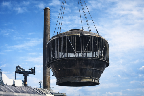
The removal assembly is sunk into the sea at a depth of 25 m as a prefabricated unit about 7.5 km apart from the beach.
This has the advantage that the quality of water is not impaired by shipping, tides and by allgaes at the collection site.
The PE pipeline (2x DN 1.200), which is connected to the removal assembly is partly laid in the harbor quay leads to the extraction pumping station (see 5.2) in the beach area.
5.2 Extraction Pumping Station
The extraction pumping station is equipped with several frequency-controlled pumps. These Pumps are used to convey the raw water to the pre-filters (see point 5.3) via 2 transport pipes (each DN 1.200) to the pre-filters (see point 5.3) in the technical area.
The transport pipes are guided parallel to the tracks.
As a result, the protected forest strip in the vicinity of the beach is only impaired in form of a strip with a width of approximately 12 m.
The extraction pumping station absorbs a surface area of approx. 15 x 30 m.
The building is completely subterranean except for a smalll access area above the surface. Note:
The following main structures 5.3 to 5.11 are arranged on the technology area
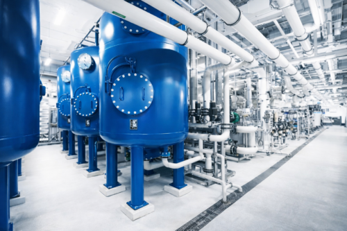
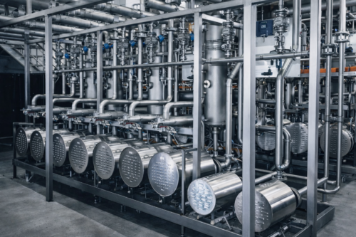
5.3 Pre filter
The pre filtration will be laid out by means of a 2 stage multiple layer filtration unit. Several filtration units will be arranged in parallel. By means of the pre filtration suspended substances and other impurities will be extracted from the seawater. The multiple layer filtration units will be arranged in the technology area. Small amounts of sulfuric acid and anti scalant will be added to the pre filtered water in order to avoid fall outs on the subsequent membranes. The dosed quantities of sulfuric acid and anti scalant do agree with the qualities of food stuffs.
5.4 Safety filtration units
The safety filtration units will be arranged in line after the pre filtration units (refer to 5.3) They are also arranged on the technology area. They will be constructed as sort of plug type filters and serve mainly for the mechanical protection of the subsequent reverse osmosis unit (refer to 5.5)
5.5 Reverse Osmosis Unit
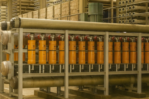
As the central unit of the seawater desalination system the membrane methodology of the reverse osmosis will be employed which is in usage for decades by now. This method profits from the osmotic pressure of salt solutions, this means the separation of seawater in drinking water (salt deficient pemeat) and salt enriched solution by means of a physical separation in the membrane which is made possible by application of a transmembrane pressure. This means the production of brine will be accomplished without the usage of chemicals. Merely the membranes have to be flushed from time to time with cleaning solutions. The cleaning solutions will be diposed of according to regulations. The enrichment of the brine is an important step in the procedure before salt can be gained from the salt-pit. The reverse osmosis unit will be partitioned in several modules. The modules will be set up in a hall in the technology area.
5.6 Water Hardening
The permeat which is depleted from salt can still not be used as drinking water. According to the WHO-regulations for drinking water small amounts of the following substances have to be added
a) lime milk (for adjustment of the water hardening)
b) chlorine (for desinfection and to protect the pipeline for the transport of drinking water to Dakar against germination)
c) a part stream of raw water before entering the reverse osmosis unit (in order to reach the desired salt content)
The administration in doses of the above mentioned substances belong to the world wide accepted standards for the production of drinking water.
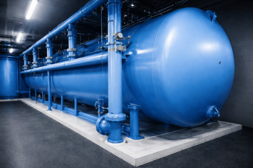
5.7 . Pumping Plant for Drinking Water
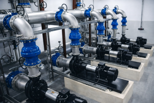
The pumping plant for drinking water consists of two containers with a capacity of 5.000 m3 and several downstream frequency operated pumps inserted in the system. All these components are arranged on the technology area.
5.8. Drinking water pipeline
The drinking water pipeline is run with 2 parallel pipes DN 1200. The pipes will be relocated in the coastal area from Lompoul to Dakar. The lines are 2,6 – 3,0 m deep and have an overlap of 1,2 m.
High point vents will be installed. The pipe diameter are large enough. Therefore no additional pumping stations are necessary. The transfer point in Dakar is coordinated with the utility company.
It is envisaged, that the new water pipelines will be introduced into existing storage facilities. As soon as the new water line in operation is taken, the old existing lines will be restored. Therefore increasing the security of supply.
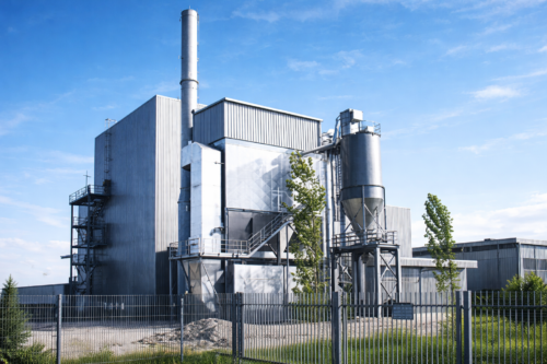
5.9. Bottling plant
In the technology area a bottling plant / beverage factory is built. 540 Mio. water bottles a year are produced. Bottled mineral water and sweet drinks are made. The beverage factory is built in a steel hall ( L x B x H = 100 x 40 x 6 m ). The bottles are stored on pallets and transported by trucks.
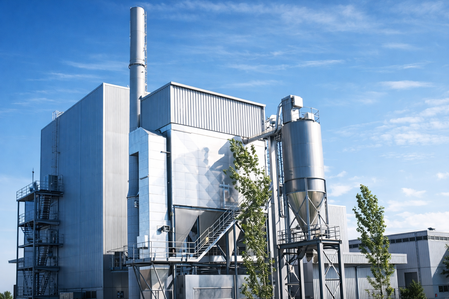
The following pictures show the planned technical area ( 30.000 m² ). It is built a new road from Lompoul to Kebemer ( T 30 ).
5.10. Concentrate Pumping station
The concentrate pumping station is installed in the technical area. The saline is primarily charged with the frequency-controlled concentrate pumps. Not usable concentrate is pumped into the sea. The location of the return point must still be coordinated. The return line is led parallel to the water line and the tracks to the beach area.
5.11. Energy Systems
Three thermal power blocks à 15 MW are provided for the electrical power supply. Two blocks are in operation and the third block is stand-by. Three blocks are planned, but initially only two blocks are built. Parallel to the planning and construction phase, solar- and wind yield measurements are carried out.
After the evaluation of the measurements it is decided, whether:
- the third block is conventionally realized as block 1+2, or
- wind turbines are installed, or
- that additional solar power plants are created, or
- that a solar thermal power plant will be built.
Decisive for the decision are economic and energetic factors.
It is provided that the power plant block 1+2 is designed with a thermal oil intermediate circuit. Thereby a coupling can be made with a solar thermal power plant. As fuel for the thermal power station blocks 1+2 coal, wood or other biomass is used. For the economic calculation no energy savings through regenerative power plants have yet been taken into account. Therefore the calculation is on the save side. Furthermore, attempts are being made to procure organic waste for a price-optimal energy generation. The combustion technology of the power plants is designed according to swiss regulations. Environmental impacts are therefore excluded.
5.12. Concentrate return
The concentrate, which cannot be used for salt production, must be returned to the sea. This is done by means of two parallel PE-lines DN 1200.
From the technical area to the beach, it is laid parallel to the raw water pipelines and the railways. The exact location of the return-points is coordinated with the environment
5.13. Saline and conveyor systems
The salt-rich concentrate is pumped into the saline. The saline has a floor area of 12 km² (2x 6 km) and is divided into several fields. The topographical interventions are thus minimized.
By natural evaporation a salt is produced, which can be used without problems for food purposes. In the salt fields the salt is conveyed with belts to the railway tracks. From there transport via container to the ships is planned. A food salt preparation is planned next to the technical area.
5.14. Port quayside with railways
For coal and salt, the following maximum turnover is calculated depending on the respective bulk weight:
Coal : 523.000m³/a Salt : 2.657.000 m³/a
Sum : 3.180.000 m³/a
At 250 working days, a daily turnover of up to 13.000 m³ is achieved with the use of 40“ containers for intermediate transport
- port - saline
- port – power plants
a daily turnover of 200 containers.
A new port will be installed to deal with these volumes. The two pipelines are laid here as well. Across this 8-10 meter wide quay with bilateral side walls lead two rails to the saline and the power stations. The port facilities are designed for bulk carriers up to panamax-class.
This means approximately one coal ship per month and one salt ship per week. By this concept is ensured that the transport is not the existing infrastructure burdened and all over the open sea will be settled.
Ships of the panamax-class have a draft of 12,5 m. A 5 km long dock is planned to ensure a natural depth of 15-17 m.
The port facility can also be used later by the fishermen of Lompoul.
